802 Commonwealth Avenue, Boston, MA
[CHRISTINA] LU JIN
Lighting | Electrical Option
BUILDING STATISTIC

Building Name
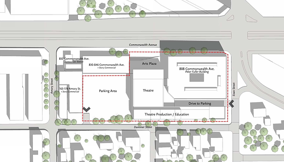
Location and Site
Building Occupant Name
Occupancy or Function Types
Size (total square feet)
Number of Stories
Primary Project Team
Dates of Construction
Project Delivery Method
Boston University School of Theater
820 Commonwealth Ave., Boston, MA
Boston University (students, faculties and guests)
Performing Arts / Education
80,000 SF
4 stories above grade; 6 total levels
Owner | Boston University
Project Manager | Stantec
Construction Manager | BOND Brothers
Building Architects | Elkus Manfredi Architects
Lighting Consultants | Auerbach Glasow French
Theatre Design | Auerbach Pollock Friedlander
MEPF Engineer | Vanderweil Engineers, LLP
Structural Engineer | Amman & Whitney
Landscape Architect | Mikyoung Kim Design
June 2016 – August 2017
Design – Bid – Build
BUILDING OVERVIEW
Boston University Theatre Center (BUTC) is a steel-beamed, glass-filled vibrant modern performance complex, located in the middle of BU’s Charles River Campus, the contrast of BUTC with its surroundings will change the dynamic tremendously and promote a more creative community.
This state-of-the-art performance complex has couple of highlighted spaces, including a featured high-bay lobby area, a large-scale multi-functional theatre space (aka. “Black Box”) with a seating capacity of up to 250 depending on the configuration of the stage, and also an exterior landscaped plaza fronting the Commonwealth Avenue.


Other than the featured spaces, BUTC also has a full complement of backstage performance/ technical support (storage, dressing rooms, production offices, kitchenette); shop spaces (scene shops, tool areas with dust collection and paint application, costume creation and storage); design and technical faculty offices; teaching spaces (classrooms, conference rooms, lighting/ audio labs); and support spaces such as restrooms, circulation and back of house areas.
Underneath the 4-story theatre center is a two-level subsurface parking garage (containing 182 parking spaces) in addition to the reconfigured landscaped surface parking lot (containing 104 spaces) makes up a total of 286 parking spaces.


HISTORICAL ELEMENTS
After a history of 33-year residence on the other side of the campus at the old Boston University Theater. This new modern performance complex – BUTC is now located in the middle of the BU’s Charles River Campus, to bring the performing art programs back close to BU College of Fine Arts (CFA). Which has allowed School of Theatre to end its long-standing tradition of cross-disciplinary collaboration through its academic outreach.
BUTC not only made it possible for the School of Theatre to be no longer split in two separate locations, but provides more opportunities for BU students, faculty, and staff to attend productions. In addition, this vibrant community could also promote a more creative environment, promise strengthened professional education, and increase the connectivity among collaborative artists at the same time. Most importantly the contrast of BUTC with its surroundings will change the dynamic tremendously and will be attractive to the student body and the general public.

SUSTAINABILITY FEATURES
The building is being designed to achieve Gold-level certification under USGBC LEED V3 2009, BUTC’s design team approaches the sustainable intent from couple of different aspects. Firstly, high performance wall material and roof constructions are used to avoid thermal bridging, also the combination of the high-performance glazing plus the daylight sensor made it possible to utilize the solar energy to the building’s advantage, and decrease its dependence on artificial light at the same time. Secondly, the use of natural ventilations could effectively bring down the air-conditioning load during favorable outdoor conditions. Thirdly, due to the diverse thermal design parameters of different types of spaces, sensitive location and definition of borders between zones are treated differently (like air curtain, etc.) to reduce thermal losses. Openings or fans for deliberate, controlled airflow are also designed between zones. In addition to the above, high efficiency HVAC systems like Demand-Controlled Ventilation, Exhaust Air Heat Recovery, Building Automation System, and Water-Side Economizers are also being considered and utilized as a contribution towards the sustainability strategies.
OVERVIEW
High-performance glazing
High-performance wall and roof constructions which avoid thermal bridging
Use of natural ventilation during favorable outdoor conditions
High-efficiency lighting design, including extensive use of LED fixtures
Sensitive location and definition of borders between zones to reduce thermal losses
Design of openings or fans for deliberate, controlled airflow between zones
Appropriate selection and evaluation of sound-absorbing materials
ENERGY EFFICIENT STRATEGIES
Demand-Controlled Ventilation
Demand controls enable the building to set back operations when a particular space is not in active use. The monitoring is connected through a CO2 sensor that indicates when occupants are present and require ventilation.
At less than full building occupancy, the DCV system can reduce ventilation air volume, thus reducing the energy required to heat or cool and dehumidify the ventilation air.
Exhaust Air Heat Recovery
With this system, heat is exchanged between the outgoing exhaust air and the incoming ventilation air. During the heating season, warm exhaust air helps to pre-heat the incoming outdoor air; during the cooling season, relatively cool exhaust air helps to pre-cool the incoming outdoor air. The heat recovery device will be between 50 percent and 75 percent efficient in capturing heat (or “coolth”) that would have otherwise been exhausted.
Building Automation System (BAS)
The design incorporates a Building Management System that can aid in the maintenance of the mechanical systems, ensuring safety and maximum energy optimization. When the system experiences an uptick of unusual energy use (as defined by the building staff), the appropriate point person for maintenance will be alerted.
High-Efficiency Chillers
The water-cooled chillers currently included in the design operate significantly more efficiently than comparable air-cooled chillers or packaged rooftop units.
Water-Side Economizer
A plate-and-frame heat exchanger will allow cooling tower condenser water to cool the building during the wintertime, also allowing the chiller plant to remain off.
Condensing Hot Water Boilers
The design includes condensing boilers, which operate at higher efficiency levels than conventional hot water boilers.
High-Efficiency Lighting
LED light fixtures are used throughout the building, saving energy compared to compact fluorescent technology.
Fan Coil Units with EC Fan Motors
Electrically-commutated (EC) fan motors allow the fan coil units (FCUs) to use less fan energy than typical FCUs.
PRIMARY ENGINEERING SYSTEMS DISCRIPTION


ELECTRICAL
CONSTRUCTION
LIGHTING
MECHANICAL
STRUCTURAL
BUILDING FOUNDATION + STRUCTURAL SYSTEM
The new building structural system is a combination of composite steel and braced frame. The composite steel system is able to reduce the construction cost of the project, the existing steel composited steel gravity system and isolated footings will be verified, reinforced and reused per the building renovation. The new structural gravity system also adopts composited steel system to reduce the building weight, slab thickness, floor vibration, and construction cost comparing with non-composited steel system. Another beauty of composite steel system is that the composited steel slab does not have long-term deflection, which is the increased deflection due to creep and shrinkage of concrete slab system. Therefore, it provides more flexibility to architectural facade and interior design.
Where brace framing will reduce the weight of building system, the new building uses steel braced frame to resist the forces caused by wind and seismic. Steel braced frame is an economical lateral system that occupies less space and has more flexibility of location, structural strength and stiffness. Due the advantages of steel braced frame, the new building structural system is able to locate the lateral system through the grid lines 2 and 5.4 in west-east direction, and grid line A and D in north-south direction without interrupting interior architectural/MEP design.
New building foundation system adopts isolated footing to resist the loads from gravity column and foundation walls. Beside the downward gravity force, the building foundation system also needs to resist the uplift forces caused by wind and seismic loads. To resolve this challenge, the mini-pile cap system is introduced by structural engineer to distribute the uplift force through the ground.
Unlike the uplift wind/seismic force, the building also experience another upward force. Thirty feet under the ground level, the hydraulic pressure becomes another challenge to the building foundation system. Even though the composited steel system is good for gravity force; for hydraulic pressure, it becomes incapable. However, there are more ways than one. The new building structure uses the 14” two way concrete slab to resist the hydraulic pressure. By placing tension reinforcement both top and bottom of slab. The two-way slab can easily to take care of the gravity force of occupancy and the hydraulic pressure from underground.
Eventually, all forces are supported by building structural system and distributed to the ground.